[ad_1]
Background
This section details the results of investigations carried out on geotextile breakwaters filled with mortar. From the previous experiments, Bag 3 is found to be the best performing model26,30. This best performing model of Bag 3 is then filled with mortar to analyse its efficacy when used as armour units of breakwater structure. In this context, the following configurations are tested in the wave flume;
-
1.
Bag 3 filled with 15% cement, stacked in single layer.
-
2.
Bag 3 filled with 20% cement, stacked in single layer.
-
3.
Bag 3 filled with 20% cement, stacked in double layers.
Wave runup studies
Wave runup height is recorded to calculate the relative runup height (Ru/H0), which is beneficial for understanding the overtopping and transmission of water over the crest of the structure. Relative runup of all tested breakwater configurations is represented in Fig. 4. This shows that breakwaters of single-layer Bag 3 with 15% cement exhibited the maximum relative runup, with double layer 20% cement-filled configuration being the least. Breakwater with single-layer 15% cement filled configuration exhibited a maximum of 15.9 and 33.33% higher relative runup with respect to those with single layer of 20% and double layer of 20% cement bags, respectively.
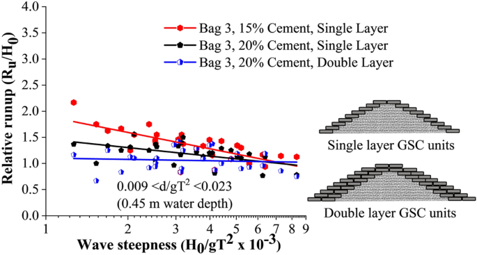
Relative runup of all tested configurations.
Relative runup vs wave height to depth ratio (H0/d) of all the tested breakwater configurations are represented in Fig. 5. This shows that single-layer breakwaters with 15% cement filled armour units had the maximum relative runup, with double layer 20% configuration being the least. This plot is helpful in analysing the efficacy of various placement modes.
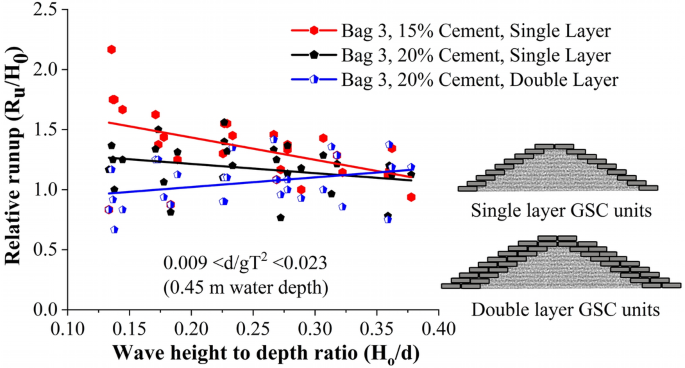
Relative runup vs wave height to depth ratio (H0/d) of all the tested configurations.
Breakwaters armoured with 15% cement-filled bags showed a tendency to break within. Those broken bags tend to readjust in the structure slope resulting in the closure of certain pore spaces. As a result, wave dissipation reduced, leading to increased runup. When the bags were filled with 20% cement, they acted like solid units, creating more pore spaces. Those solid units provided no scope of readjustments, as a result, the pore spaces were not affected. This promoted increased wave dissipation on the structure slope resulting in the reduced runup. Further, when an additional layer was provided, the porosity of the structure increased, resulting in further wave dissipation on the structure slope. This resulted in the reduced runup rates of double-layer arrangement.
Wave rundown studies
Wave rundown is helpful in understating the behaviour of water retreating from the structure surface. The relative rundown of all tested configurations is represented in Fig. 6. This shows that single-layer breakwaters armoured with 15% cement showed the maximum relative rundown, with double-layer breakwater structure of 20% cement-filled units being the least. Bag 3, 15% cement-filled single layer configuration represented 5 and 31.25% higher relative rundown with respect to single layer 20% (cement fill) and double layer 20% (cement fill) arrangements respectively. The relative rundown vs wave height to depth ratio (H0/d) of all the tested configurations is represented in Fig. 7. This shows that breakwaters armoured with single-layer 15% cement fill, showed the maximum relative rundown, with double layer 20% cement filled configuration being the least. This plot is useful in analysing the efficacy of various placement modes.
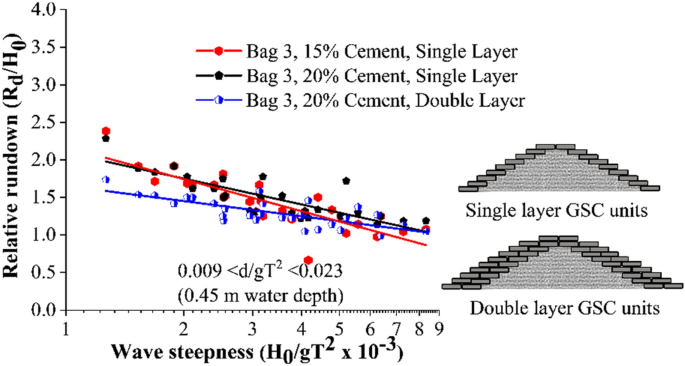
Relative rundown of all tested configurations.
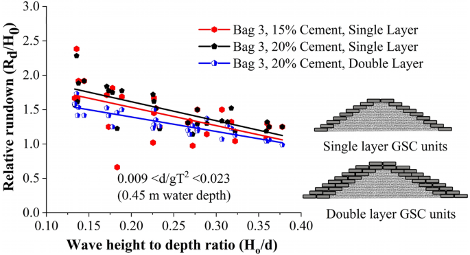
Relative rundown vs wave height to depth ratio (H0/d).
Single layer placements nearly represent a similar rundown behaviour, a maximum of 5% variation. When the armour units are arranged in double layers, increased porosity helped in wave dissipation, as a result, wave rundown decreased for double-layer structures.
Reflection analysis
Analysis of wave reflection from the breakwater are presented in this section. The three probes method by Isaacson53 is adopted in the estimation of reflection coefficient Kr. The variation of Kr with wave steepness parameter for all the test cases is represented in Fig. 8. It is evident that all the test cases exhibited lower Kr values compared with convention breakwaters, as appeared in Zanuttigh and van der Meer14. Breakwater structure with single-layer configuration with 20% cement fill showed the maximum reflection, up to 76% higher than other models. The fitted curves exhibit a poor correlation coefficient, which is just up to 19%. Decreased Kr values are a result of increased porosity and consequent increase in wave dissipation on the structure slope.

Calculated Kr values for all the tested cases.
Stability and damage analysis
It has to be noted that when the geotextile containers are filled with mortar, the resulting breakwater structure produces more pore spaces than containers with sand alone (Fig. 9). Internal displacement of sand, when subjected to wave action, has been stopped due to the cementation process. Additionally, the hard units tend to be comparatively stable than its sand alone counterparts. In most cases, pull-out was observed as the major failure mode. The process of pulling out of containers occur due to wave attack on armour units. According to Recio56, interface friction is the major factor controlling the pullout of GSC units. The friction properties of the material and contact area between two containers control the interface friction. In the case of cement-filled bag, the bags become bulky after solidification reducing the contact area between two containers, as a result, interface friction reduces, leading in increased pullout of GSC armour units.
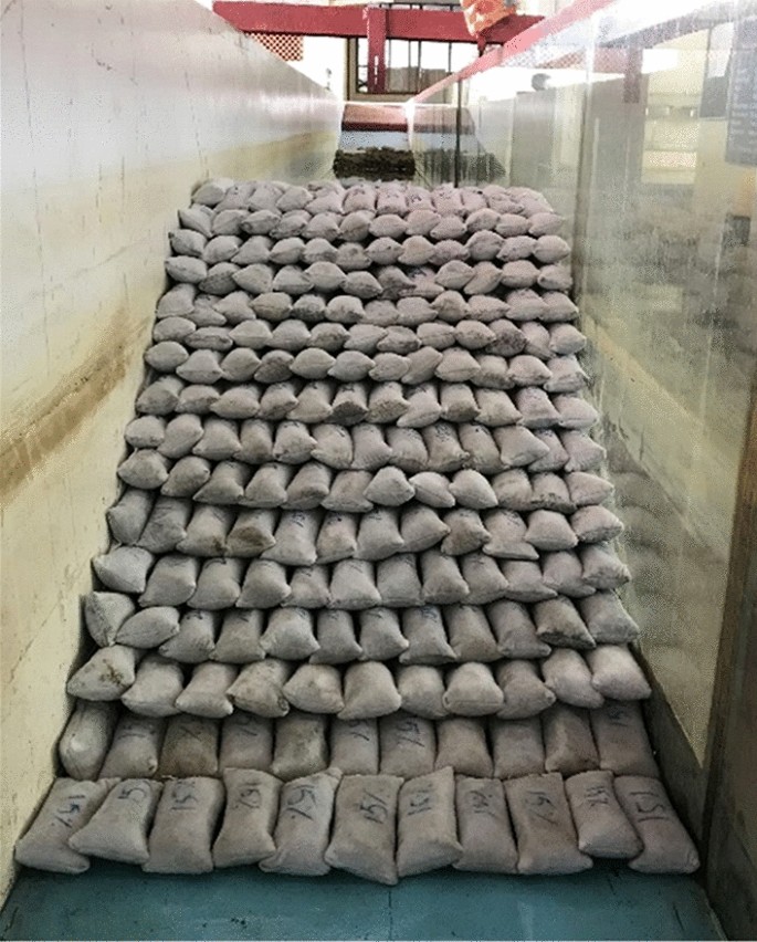
Image showing sand container filled with 15% cement and arranged to a single layer. Note the bulkiness of the units contributing to higher porosity.
As reported by Dassanayake and Oumeraci54 and Elias et al.30, incipient motion (DC1) curves can serve as a suitable tool to demarcate the stability of a particular case. Cw value is calculated for each incipient motion points Eq. (2) and its average value is used in (3) for drawing the stability curves.
$${text{C}}_{{text{w}}} {text{ = N}}_{{text{s}}} cdot sqrt {{upxi }_{{0}} }$$
(2)
$${text{N}}_{{text{s}}} { = }frac{{{text{C}}_{{text{w}}} }}{{sqrt {{upxi }_{{0}} } }}$$
(3)
where Ns is the stability number and ξ0 is the surf similarity parameter and is represented by (4) and (5). Hs is the incident significant wave height, ρw and ρGSC correspond to the density of seawater and GSC. D is the thickness of armour layer given by l.sinα, where l is the length of GSC armour units, α is the slope angle of the geosynthetic structure, L0 is the deepwater wavelength, equals to gT2/2π, where T is the wave period.
$$N_{s} = frac{{H_{s} }}{{(frac{{rho_{GSC} }}{{rho_{w} }} – 1) cdot D}}$$
(4)
$$xi_{0} = frac{tan alpha }{{sqrt {frac{{H_{0} }}{{L_{0} }}} }}$$
(5)
Incipient motion curves are obtained for Bag 3 filled to 15% cement, arranged to a single layer as shown in Fig. 10. Experimentations are carried out at three different relative water depths 0.007 < d/gT2 < 0.018 (0.35 m), 0.008 < d/gT2 < 0.020 (0.40 m) and 0.009 < d/gT2 < 0.023 (0.45 m). As seen from the graph, stability at lowest water depth (0.35 m) was found to be 25 to 29% higher than at 0.40 and 0.45 m water depths respectively. Higher wave activity, wave energy at increased depth of water can be the possible reason for this. Moreover, wave runup and rundown will be higher at higher depths of water resulting in increased instability.
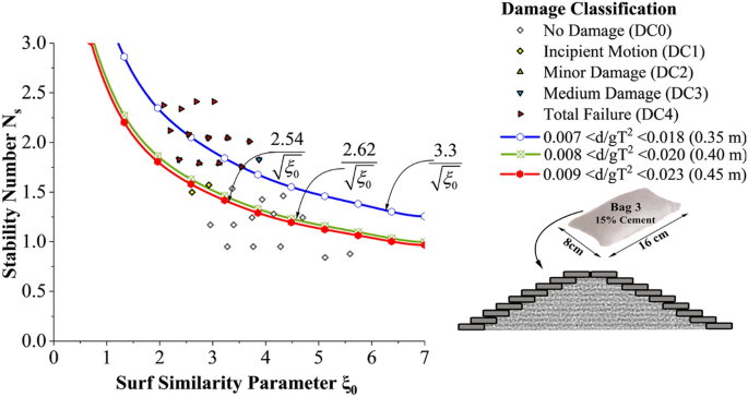
Incipient motion curves for Bag 3 filled with 15% cement, arranged to a single layer.
Incipient motion curves are obtained for Bag 3 filled to 20% cement, arranged to a single layer in Fig. 11. Experimentations are carried out at three different relative water depths 0.007 < d/gT2 < 0.018 (0.35 m), 0.008 < d/gT2 < 0.020 (0.40 m) and 0.009 < d/gT2 < 0.023 (0.45 m). as seen from the graph, stability at lowest water depth (0.35 m) was found to be 2.4 to 3.5% higher than at 0.40 and 0.45 m water depths respectively. Wave runup was smaller at 0.35 m water depth thus deformations occurred during runup will be comparatively lower.
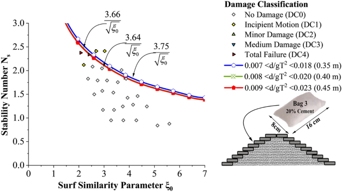
Incipient motion curves for Bag 3 filled with 20% cement, arranged to a single layer.
But the deviation of stability is found to be comparatively lesser than 15% cement-filled case. Moreover, when the cement content in bags increased from 15 to 20%, the stability of the structure shot up to a maximum of 43.3%. Incipient motion curves obtained for Bag 3 filled with 20% cement, arranged in double layers are shown in Fig. 12. Experimentations are carried out at three different relative water depths 0.007 < d/gT2 < 0.018 (0.35 m), 0.008 < d/gT2 < 0.020 (0.40 m) and 0.009 < d/gT2 < 0.023 (0.45 m). as seen from the graph, stability at lowest water depth (0.35 m) was found to be 4.5 to 8.1% higher than at 0.40 and 0.45 m water depths respectively. Higher wave activity and wave energy at deeper depths may be the possible reason. Moreover, when the number of layers increased from one to two, a considerable decrease in stability, up to 23.6%, is exhibited. The major reasons behind these observations will be discussed in the subsequent sections.
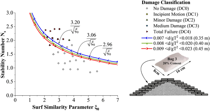
Incipient motion curves for Bag 3 filled with 20% cement, double layer.
As far as the hydraulic performance and stability are considered, breakwater structures with GSC armour units filled with 20% cement are observed to perform better than those units filled with 15% cement. Therefore, studies on structures with double layer GSC units filled with 15% cement are not carried out in the present study.
Effect of the number of layers and cement percentage
The effect of the number of layers and cement percentage has been tested in this section. Stability curves of all experimented configurations are analysed for a relative water depth 0.007 < d/gT2 < 0.018 (0.35 m actual water depth in flume) in Fig. 13. 20% cement-filled bags arranged in single layer exhibited increased stability, 13.63 and 17.18% higher than 15% cement single layer and 20% cement double-layer configurations, respectively.
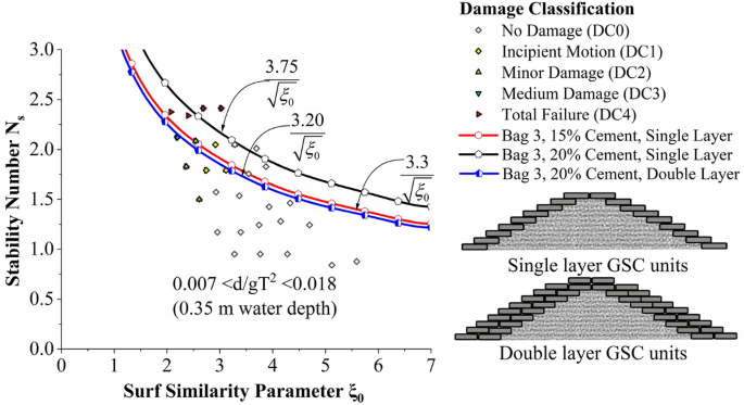
Stability curves of all experimented configurations for a relative water depth 0.007 < d/gT2 < 0.018 (0.35 m actual water depth in flume).
Stability curves of all experimented configurations are analysed for a relative water depth 0.008 < d/gT2 < 0.020 (0.40 m actual water depth in flume) in Fig. 14. 20% cement-filled bags arranged to single layer exhibited the highest stability, 39.6 and 19.6% higher than 15% cement single layer and 20% cement double-layer configurations, respectively. Stability curves of all experimented configurations are analysed for a relative water depth 0.009 < d/gT2 < 0.023 (0.45 m actual water depth in flume) in Fig. 15. 20% cement-filled bags arranged in a single layer exhibited the highest stability, 43.3 and 22.9% higher than 15% cement single layer and 20% cement double-layer configurations, respectively.
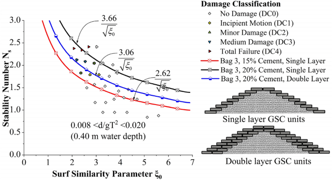
Stability curves of all experimented configurations for a relative water depth of 0.008 < d/gT2 < 0.020 (0.40 m actual water depth in flume).

Stability curves of all experimented configurations for a relative water depth 0.009 < d/gT2 < 0.023 (0.45 m actual water depth in flume).
From the above analysis, it has been observed that when cement content is increased from 15 to 20%, there is a considerable increase in stability, i.e. 13.6 to 43.3%. Sand bag structure with 20% cement content exhibited higher strength. The strength of the bag increased because of an increased percentage of cement in it. This may be the reason as it could withstand higher wave activity. However, the hardened material inside certain 15% cement-filled bags showed a tendency to break within the container, making it vulnerable to detachment on higher wave activity.
Similarly, when 20% cement-filled bags are altered from single layer to double layer, 17.18 to 22.9% decrease in stability is observed. This observation contradicted the general concept that stability increases when the number of outer armour layers increases. The reduction in stability of double-layer structure may be mainly attributed to the lack of friction experienced by the outer armour layer. As a result, units from the outer layer tend to get detached at lower wave heights as shown in Fig. 16. Bags with broken units inside practically looked the same when photographed. A case of armour deformation has been added and shown in Fig. 16.
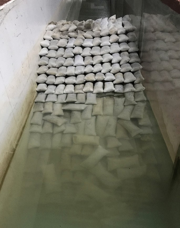
Image showing detached GSC units from the outer layer of breakwater model.
Comparison of cement and sand-filled configurations with other configurations
Comparative analysis of wave runup
Figure 17 shows the comparative analysis of the runup behaviour of cement-filled GSC armour units with other basis GSC armour configurations as discussed in Elias et al.30. The runup curves tend to vary from 0.5 to 2.7 on a scale of relative runup rate (Ru/H0), of double-layer configuration of Bag 3 armour (20% cement-filled) showing the least runup rates and parallelly placed configuration showing the highest runup rates. Out of all tested configurations, runup rates are the lowest for cement-filled arrangements. This is due to the increased wave dissipation over the structure slope resulting in reduced runup rates because of higher structure porosity. Cement-sand filled structures experience higher porosity as there is no scope for readjustments so that the pores can be covered, as in the case of GSCs. Closer observations in Fig. 18 reveal that relative wave runup is considerably reduced as the number of layers increases from one to two. Single-layer Bag 3 structure with armour filled with sand alone exhibited a 13.15% to 8% reduction in runup rates compared with the double-layer arrangement. Similarly, up to 31% reduction is experienced in the runup rates on Bag 3 cement-sand filled double-layer configuration compared to its single layer counterpart. As the layer increases, more pore spaces are created, accelerating wave dissipation over the structure, thus reducing runup.
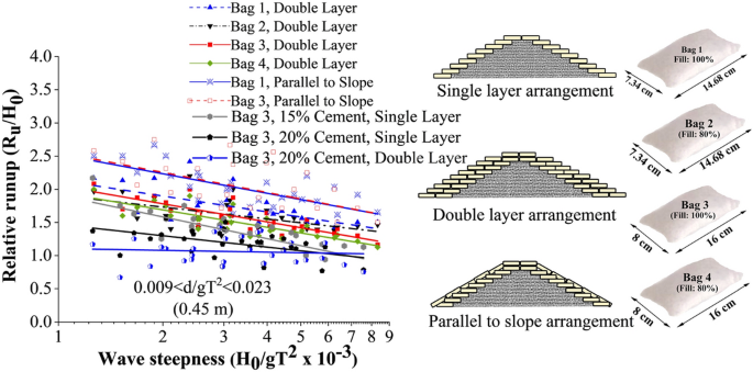
Comparative analysis of runup behaviour of all the tested configurations.
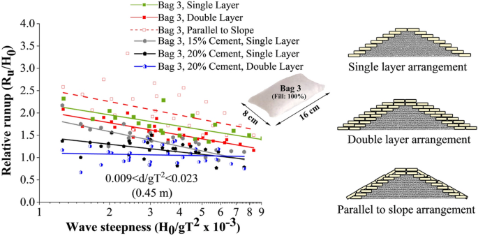
Relative wave runup for various placement modes of Bag 3.
As far as placement method is compared, slope-parallel placement is observed to possess higher runup rates. Slope parallel placement exhibited up to 31.5% and 16.27% increased relative runup compared to double and single-layer structures. The main reason behind this observation is the continuous covering mechanism in slope-parallel placement, reducing the porosity of the structure. As a result, runup increases and more wave energy gets reflected due to its inability to dissipate energy.
Comparative analysis of wave rundown
As far as wave rundown is considered, the slope parallel placements exhibit the maximum value, which ranges up to 2.5 times the incident wave height (see Fig. 19). The structures indicate the least rundown values with 20% cement content (relative rundown ranging from 1.1 to 1.5). The rundown values exhibited by all other models lie between these two cases. The main reason behind high rundown is the continuous covering in slope-parallel placement, reducing the porosity of the structure. As a result, water glides and remains on the structure slope without getting absorbed or dissipated through the pores. Also, 20 to 30% decrease in rundown is exhibited as the size of the armour unit increased. As discussed in the previous sections, increasing the porosity of the structure with increasing armour unit size may be the significant contributing factor to the reduced runup.
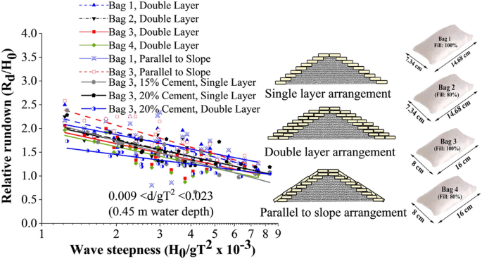
Comparative analysis of rundown behaviour of all the tested configurations.
Comparative analysis of reflection
The reflection values appear scattered, as illustrated in Fig. 20. One can observe that all other tested configurations exhibit lower reflection rates than the conventional breakwater except GSC single layer configuration. It has to be noted that mortar filled configurations exhibit lower reflection rates, with a maximum reflection coefficient Kr of 0.2. Increased porosity, in that case, could be the possible reason for the reduction in reflection.
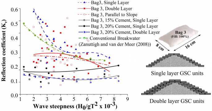
Comparison of stability
Stability curves for all the tested GSC breakwater configurations help analyse the efficacy of various placement techniques. In the present investigation, structure with ‘Bag 3’ armour is experimented within all types of arrangements, including single and double layers, slope parallel placements and cement-sand filling. Therefore, stability curves of Bag 3 armour with all the tested arrangements for 0.45 m water depth have been represented in Fig. 21. 0.45 m depth was the most damaging depth among all the experimentation cases, therefore, critical cases of stability tests were only investigated. Cement 20% single layer configuration shows the maximum stability, with slope parallel placements and single layer (15% cement) case being the weakest.
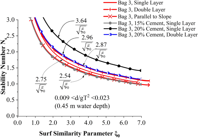
Stability curves for Bag 3 with all the tested arrangements.
As observed, when GSC units are filled with cement, single-layered structures were up to 22% more stable than double-layer structures. This is contradictory to the fact that stability increases with the number of layers. The possible reason for this instability can be the lack of friction between the layers, as geotextiles are used. Additionally, these GSC units formed pillow-shaped solids (susceptible to easy displacement) with poor interlocking when the cement-sand mixture solidified within the bags. Units filled with sand alone (see “Stability and damage analysis” section) showed lesser stability when compared with cement-filled units. Out of all tested configurations, slope parallel placement showed the least stability due to decreased porosity and increased runup and destabilising activity on structure slope.
[ad_2]
Source link


